One of the most common landscape diagrams that I see is the application communication diagram. This diagram does what it says on the metaphorical tin – it answers the simple question:
“What applications talk to what other applications?”
Given the above, there’s only one type of entity that such a diagram shows – applications. Both TOGAF and ArchiMate offer such a diagram type; in TOGAF it is an Application Communication Diagram, in ArchiMate it is usually an Application Collaboration Diagram. Regardless, it’s all about communication paths.
Which would seem to make life easy, but in practice, the biggest challenge that we face with a diagram like this is the sheer number of lines that exist. Even in a fairly simple environment with only 100 significant applications, the number of possible paths becomes 4590. In practice, the number of connections is nowhere near that high, but the fact remains, the greatest challenge such a diagram faces is to not look like an explosion in a cable factory.
The key to accomplishing this is to minimize the length of connecting lines, and minimize the extent to which they overlap. Fortunately, there are a couple of rules of thumb and techniques that we can apply based on the nature of corporate systems –specifically, the existence of what I’ll be calling core systems.
The large organizations that I’ve worked with have all had a couple of core applications that most other tie into. In a travel company such as an airline, the core application is the reservations system – PARS or some other type. In telecoms, the rating and billing system is the core. In banking it’s a core banking system such as T24.
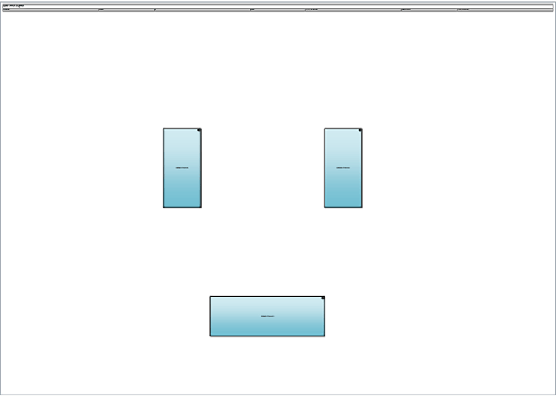
We use these couple of core systems that have the largest number of connections as our anchor for the diagram, placing them in the center of the diagram. We also need to make them somewhat larger than most applications because of the sheer number of connections that they have.

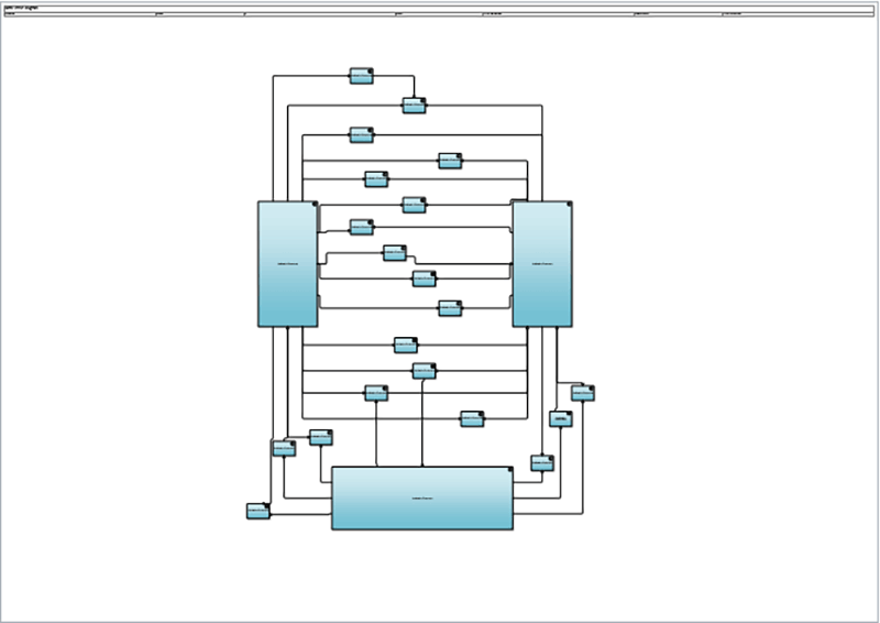
The next step is to identify the applications that only connect to the core applications. A surprising number of application will only connect to one, or perhaps two of the core applications. These applications that only talk to two of the core applications can be placed between them, so that the communication paths are minimized – this minimizes the number of confusing overlaps.

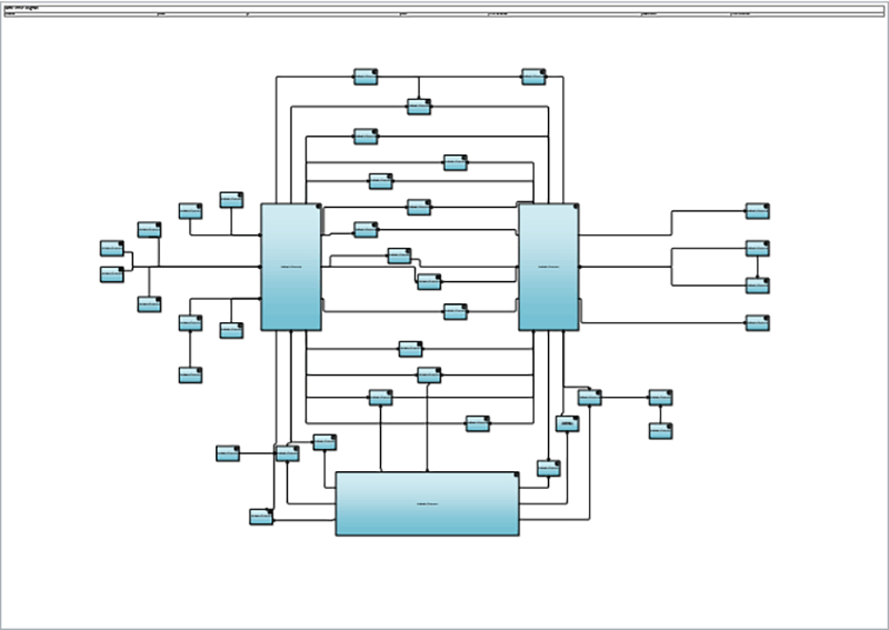
At the same time, those applications that only communicate with one of the core applications can be collected together on one side of the core application in question and linked to it.
Last of all, we can add in communication paths between existing ‘tier 2’ applications (meaning those that connect to one or more of the core applications), those applications with no connections, and those applications that connect to the tier 2 applications

Deciding how to lay out the spider web of connection paths between applications can seem an insurmountable task, but in this post I’ve presented a methodology that I’ve found helpful to apply some order to the mass of strands that confronts us when considering the application communication paths seen in a large organization.
Come back next week, when I'll be discussing the last diagram in this series, the Deployment Diagram.


.png)


