

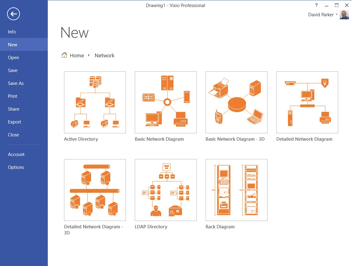
The top three uses of Visio in business are Process Flows, Organization Charts, and Network Diagrams. In this article I will discuss simple versions of the latter, which can be found under the Network category. There are some templates in the standard edition, but there are more templates and stencils in the professional edition, and besides, that also has the Link Data to Shapes feature.
In my career, I have diagrammed many types of network diagrams with Visio, and almost all of them have been linked to data, and most of them have been semi-automatically created with a bit of code. I have diagrammed network connections, data centre layouts, rack elevations and office floor plans, complete with cable trays.
All of these can be created from data, and/or they could be used to generate data, such as an inventory or a proposed network topology. However, I do get disappointed when I see IT professionals draw network diagrams manually with Visio, and don’t leverage the other great capabilities.
The Detailed Network Diagram template comes with seven stencils pre-docked each with a number of master shapes that already contain a varying list of Shape Data rows. It also comes with three pre-designed reports.
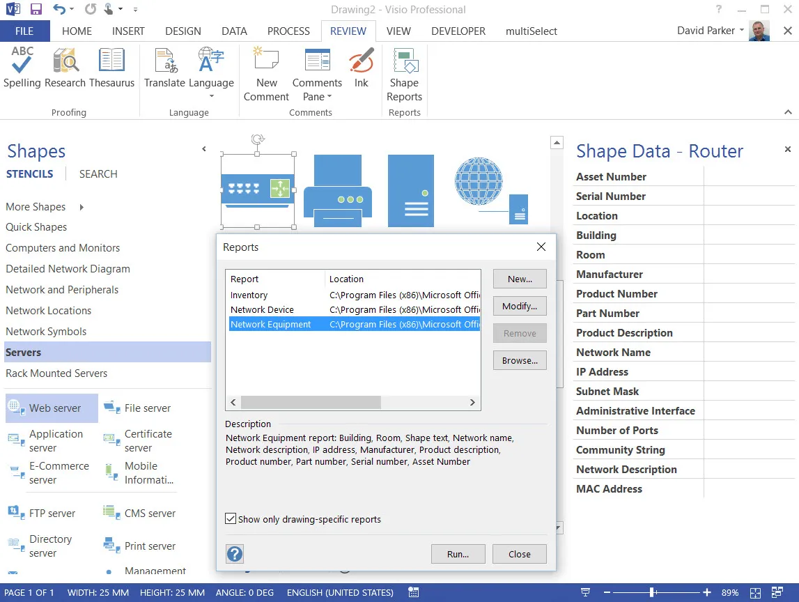
So, I first make a decision about the use of Shape Data. Are the Shape Data rows providing the information required, or do I need less or more? I like to store most of my data in Excel, Access, SharePoint or SQL Server, so, if possible, I would prepare the column headings to match exactly those that are labels in the network shapes.
There are many free and paid for tools for scanning a network available, and most of them can output the results to a text or XML file. Devices communicate on a network because they are software assigned a unique identifier (Internet Protocol address) to each connection. The connected port is usually on a hardware component that is hardware assigned (Media Access Protocol address). A laptop, for example, could be connected via an Ethernet cable, Wi-Fi or Bluetooth to a network. Each method will have a different IP address and MAC address, but they are all on the same device. The data available in each scanning tool output varies tremendously, but they will all have an IP address and MAC address. Here are three free tools showing examples of their interfaces.
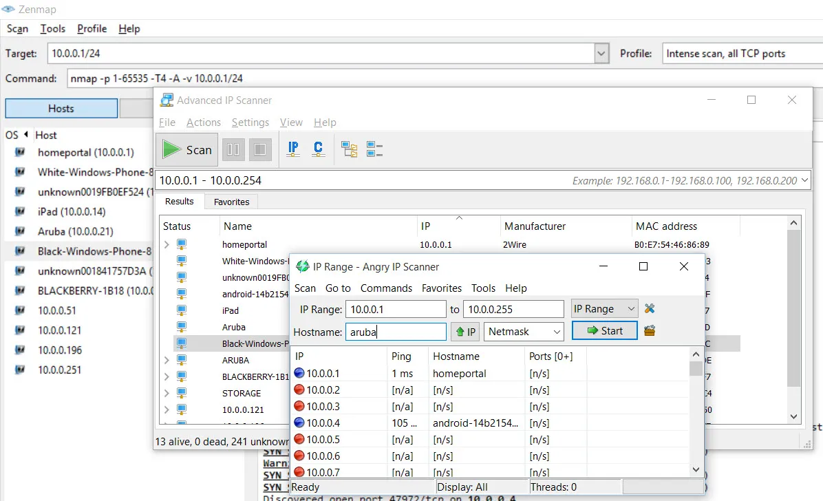
However, I know most of my devices by a more English-like name, and some of the tools will also list this, or something similar. In any case, these tools are useful for checking against a list of known devices because one way that company data can be stolen is for a rogue device to be installed on a network.
The network equipment master shapes all have at least an IP Address and a MAC Address shape data rows, but it is probable that some devices will have multiple IP addresses and MAC addresses because they have more than one way of connecting to a network. A device, however, may only have a single Asset Number, Serial Number or Network Name. Therefore, it could be more correct to assign the IP/MAC Address combination to a connector in the Visio network diagram, and perhaps assign the primary IP/MAC address combination to the device shape.
Not all devices are physical either, because there are an increasing number of virtual devices, such as Hyper-V machines nowadays. These will also have a unique IP/MAC address combination, and they too can be a risk because, for example, they may be running an application that is essential to a business process, and they can be hosted on a portable device easily.
In addition to the active elements on a network, there may be passive ones, such as non-intelligent patch panels, which serve to provide the ability to connect a cable from a source to a target, such as connecting ports from a switch to outlets in a floor box. I may want to indicate physical connections between ports in my network diagram, because they may be important in trouble shooting problems.
So, understanding a network and the status of devices and connections between them can be an extremely valuable aid to the smooth running of technology within an environment, and Visio diagrams linked to data are a an effective method for this.
Once you have a network diagram, it is possible to be continuously checking the status of IP addresses on the network with other applications, or even with simple code like https://msdn.microsoft.com/en-us/library/aa394350(v=vs.85).aspx.
Summary
In this article, I have briefly explained how to create master shapes and stencils. I have also described how existing masters can be amended locally within the Document Stencil. The use of master shapes in Visio is the key to speed, efficiency and maintainability.

.webp)